|
|
|
| Title | Draw three interlocked 3-D blocks with Direct3D in Visual Basic 2005 |
|---|
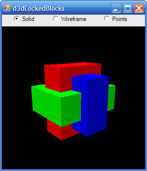
| Description | This example shows how to draw three interlocked 3-D blocks with Direct3D in Visual Basic 2005. |
|---|
| Keywords | Direct3D, DirectX, blocks, interlocked, hidden surface removal, z-buffer, Visual Basic 2005 |
|---|
| Categories | Graphics, VB.NET |
|---|
|
|
 Add a module to the program and create the following Sub Main. Change the project to start by executing Sub Main.
|
|
Module SubMain
    ' Prepare Direct3D and run the event loop.
    Public Sub Main()
        ' Make the form.
        Dim frm As New RenderForm

        ' Initialize Direct3D.
        If frm.InitializeGraphics() Then
            frm.Show()

            ' While the form is valid,
            ' render the scene and process messages.
            Do While frm.Created
                frm.Render()
                Application.DoEvents()
            Loop
        End If
    End Sub
End Module
|
|
|
Change the name of the original form to RenderForm and give it the following InitializeGraphics subroutine. This routine initializes Direct3D and creates a device on which to draw. It also calls subroutine CreateVertexBuffer to define the three-dimensional vetex data.
|
|
' The Direct3D device.
Private m_Device As Device

' Data variables.
Private Const NUM_BLOCKS As Integer = 3
Private Const NUM_RECTANGLES As Integer = NUM_BLOCKS * 6
Private Const NUM_TRIANGLES As Integer = NUM_RECTANGLES * 2
Private Const NUM_POINTS As Integer = 3 * NUM_TRIANGLES

' The vertex buffer that holds drawing data.
Private m_VertexBuffer As VertexBuffer = Nothing

' Initialize the graphics device. Return True if successful.
Public Function InitializeGraphics() As Boolean
    Dim params As New PresentParameters
    params.Windowed = True
    params.SwapEffect = SwapEffect.Discard
    params.EnableAutoDepthStencil = True            ' Depth
        ' stencil on.
    params.AutoDepthStencilFormat = DepthFormat.D16

    ' Best: Hardware device and hardware vertex processing.
    Try
        m_Device = New Device(0, DeviceType.Hardware, _
            pic3d, _
            CreateFlags.HardwareVertexProcessing, params)
        Debug.WriteLine("Hardware, " & _
            "HardwareVertexProcessing")
    Catch
    End Try

    ' Good: Hardware device and software vertex processing.
    If m_Device Is Nothing Then
        Try
            m_Device = New Device(0, DeviceType.Hardware, _
                pic3d, _
                CreateFlags.SoftwareVertexProcessing, _
                    params)
            Debug.WriteLine("Hardware, " & _
                "SoftwareVertexProcessing")
        Catch
        End Try
    End If

    ' Adequate?: Software device and software vertex
    ' processing.
    If m_Device Is Nothing Then
        Try
            m_Device = New Device(0, DeviceType.Reference, _
                pic3d, _
                CreateFlags.SoftwareVertexProcessing, _
                    params)
            Debug.WriteLine("Reference, " & _
                "SoftwareVertexProcessing")
        Catch ex As Exception
            ' If we still can't make a device, give up.
            MessageBox.Show("Error initializing Direct3D" & _
                _
                vbCrLf & vbCrLf & ex.Message, _
                "Direct3D Error", MessageBoxButtons.OK)
            Return False
        End Try
    End If

    ' Turn off D3D lighting because
    ' we set the vertex colors explicitly.
    m_Device.RenderState.Lighting = False

    ' Turn on the Z-buffer.
    m_Device.RenderState.ZBufferEnable = True

    ' Cull triangles that are oriented counter clockwise.
    m_Device.RenderState.CullMode = Cull.CounterClockwise

    ' Make points bigger so they're easy to see.
    m_Device.RenderState.PointSize = 4

    ' Start in solid mode.
    m_Device.RenderState.FillMode = FillMode.Solid

    ' Create the vertex data.
    CreateVertexBuffer()

    ' We succeeded.
    Return True
End Function
|
|
|
Subroutine CreateVertexBuffer calls MakeBlock to add points defining the three interlocking blocks.
|
|
' Create a vertex buffer for the device.
Public Sub CreateVertexBuffer()
    ' Create a buffer.
    m_VertexBuffer = New VertexBuffer( _
        GetType(CustomVertex.PositionColored), _
        NUM_POINTS, m_Device, 0, _
        CustomVertex.PositionColored.Format, _
        Pool.Default)

    ' Lock the vertex buffer.
    ' Lock returns an array of positionColored objects.
    Dim vertices As CustomVertex.PositionColored() = _
        CType(m_VertexBuffer.Lock(0, 0), _
            CustomVertex.PositionColored())

    ' Make the vertexes.
    Dim i As Integer = 0

    ' X block.
    MakeBlock(vertices, i, _
        Color.FromArgb(255, 0, 255, 0), _
        Color.FromArgb(255, 0, 205, 0), _
        Color.FromArgb(255, 0, 158, 0), _
        2, 0.75, 1.5)

    ' Y block.
    MakeBlock(vertices, i, _
        Color.FromArgb(255, 255, 0, 0), _
        Color.FromArgb(255, 205, 0, 0), _
        Color.FromArgb(255, 158, 0, 0), _
        1.5, 2, 0.75)

    ' Z block.
    MakeBlock(vertices, i, _
        Color.FromArgb(255, 0, 0, 255), _
        Color.FromArgb(255, 0, 0, 205), _
        Color.FromArgb(255, 0, 0, 158), _
        0.75, 1.5, 2)

    m_VertexBuffer.Unlock()
End Sub
|
|
|
Subroutine MakeBlock calls MakeTriangle to make the triangles that define a block.
|
|
' Add triangles to the vertex buffer to define a block.
Private Sub MakeBlock(ByVal vertices() As _
    CustomVertex.PositionColored, ByRef i As Integer, _
    ByVal clr0 As Color, ByVal clr1 As Color, ByVal clr2 As _
        Color, _
    ByVal xwid As Single, ByVal ywid As Single, ByVal zwid _
        As Single)

    MakeTriangle(vertices, i, clr0, _
        -xwid, ywid, -zwid, _
        -xwid, ywid, zwid, _
        xwid, ywid, zwid)
    MakeTriangle(vertices, i, clr0, _
        xwid, ywid, zwid, _
        xwid, ywid, -zwid, _
        -xwid, ywid, -zwid)

    ... other calls to MakeTriangle omitted ...

End Sub
|
|
|
Subroutine MakeTriangle actually adds the vertices to the vertex buffer.
|
|
' Add a triangle to the vertex buffer.
Private Sub MakeTriangle(ByVal vertices() As _
    CustomVertex.PositionColored, ByRef i As Integer, ByVal _
    clr As Color, _
    ByVal x0 As Single, ByVal y0 As Single, ByVal z0 As _
        Single, _
    ByVal x1 As Single, ByVal y1 As Single, ByVal z1 As _
        Single, _
    ByVal x2 As Single, ByVal y2 As Single, ByVal z2 As _
        Single)

    vertices(i).X = x0
    vertices(i).Y = y0
    vertices(i).Z = z0
    vertices(i).Color = clr.ToArgb
    i += 1

    vertices(i).X = x1
    vertices(i).Y = y1
    vertices(i).Z = z1
    vertices(i).Color = clr.ToArgb
    i += 1

    vertices(i).X = x2
    vertices(i).Y = y2
    vertices(i).Z = z2
    vertices(i).Color = clr.ToArgb
    i += 1
End Sub
|
|
|
The form's Render method draws the data. It begins a Direct3D scene and then calls subroutine SetupMatrices to define the world, view, and projection transformations. It then calls the Direct3D device's DrawPrimitives method to draw the data.
|
|
' Draw.
Public Sub Render()
    ' Clear the back buffer and the Z-buffer.
    m_Device.Clear(ClearFlags.Target Or ClearFlags.ZBuffer, _
        Color.Black, 1, 0)

    ' Make a scene.
    m_Device.BeginScene()

    ' Draw stuff here...
    ' Setup the world, view, and projection matrices.
    SetupMatrices()

    ' Set the device's data stream source (the vertex
    ' buffer).
    m_Device.SetStreamSource(0, m_VertexBuffer, 0)

    ' Tell the device the format of the vertices.
    m_Device.VertexFormat = _
        CustomVertex.PositionColored.Format

    ' Draw the primitives in the data stream.
    m_Device.DrawPrimitives(PrimitiveType.TriangleList, 0, _
        NUM_TRIANGLES)

    ' End the scene and display.
    m_Device.EndScene()
    m_Device.Present()
End Sub
|
|
|
Subroutine SetupMatrices defines the world, view, and projection transformations. It makes the world transformation rotate the data around the Y axis once every 4 seconds. It makes a view transformation that assumes the "camera" is located at position (0, 3, -10) and looking at the origin. Finally it makes the projection transformation use a Pi / 4 radian field of view.
|
|
' Setup the world, view, and projection matrices.
Private Sub SetupMatrices()
    ' World Matrix:
    Const TICKS_PER_REV As Integer = 4000
    Dim angle As Double = Environment.TickCount * (2 * _
        Math.PI) / TICKS_PER_REV
    m_Device.Transform.World = Matrix.RotationY(CSng(angle))

    ' View Matrix:
    m_Device.Transform.View = Matrix.LookAtLH( _
        New Vector3(0, 3, -10), _
        New Vector3(0, 0, 0), _
        New Vector3(0, 1, 0))

    ' Projection Matrix:
    ' Perspective transformation defined by:
    '       Field of view           Pi / 4
    '       Aspect ratio            1
    '       Near clipping plane     Z = 1
    '       Far clipping plane      Z = 100
    m_Device.Transform.Projection = _
        Matrix.PerspectiveFovLH(Math.PI / 4, 1, 1, 100)
End Sub
|
|
|
This is a very complicated example and only key elements of code are shown here. Download the example to see further details. Also watch for my upcoming articles at DevX for a much more detailed explanation.
|
| |

|
| |
|
|